§ 1.2 Module 1 — The Station in One Picture
Anatomy at a Glance
Water is not lifted because we want it lifted. It is lifted because the ground ran out of fall.Module 1
By the end of this lesson
- Trace one parcel of water through every element of a station in order
- Name the function each element exists to perform
- Distinguish elements that are hydraulic from those that are operational
A pump station is one machine with about eleven parts, and the parts sit in a fixed order because water can only meet them in one order. This lesson walks a single parcel through all of them, names the failure each part exists to prevent, and then separates the elements that hydraulics sizes from the elements that hydraulics only pays for. Nothing is designed here. The point is to have the whole object in your head, with the right words attached to it, before Module 2 begins putting numbers on any of it.
The anatomy is older than the vocabulary
Joseph Bazalgette, chief engineer to the Metropolitan Board of Works, gave London an intercepting sewer system whose southern arm ended at Crossness Pumping Station on the Erith marshes, opened on 4 April 1865 by the Prince of Wales, the future Edward VII. Its four rotative beam engines were built by James Watt & Co. and named Victoria, Prince Consort, Albert Edward and Alexandra. Abbey Mills, on the north side of the river, followed in 1868.
Crossness has the anatomy of this lesson in it already. Flow arrived by gravity down the Southern Outfall Sewer, because the sewer was built on the last of the available fall. The engines lifted it, because at Erith there was no fall left. A covered reservoir stored it, and it was released to the Thames on the ebb tide — an operational decision about when, laid on top of a hydraulic decision about how far up. Gravity in, lift, store, discharge on a schedule: a modern station is the same four moves with a screen added and a beam engine replaced.
The one element on the list below that Bazalgette did not have is the submersible pump. The Swedish firm Flygt dates its first submersible drainage pump to 1947; it is why a small station today can be a single wet well with no dry chamber and no engine house at all — and why the suction pipe, which this lesson names, sometimes does not physically exist.
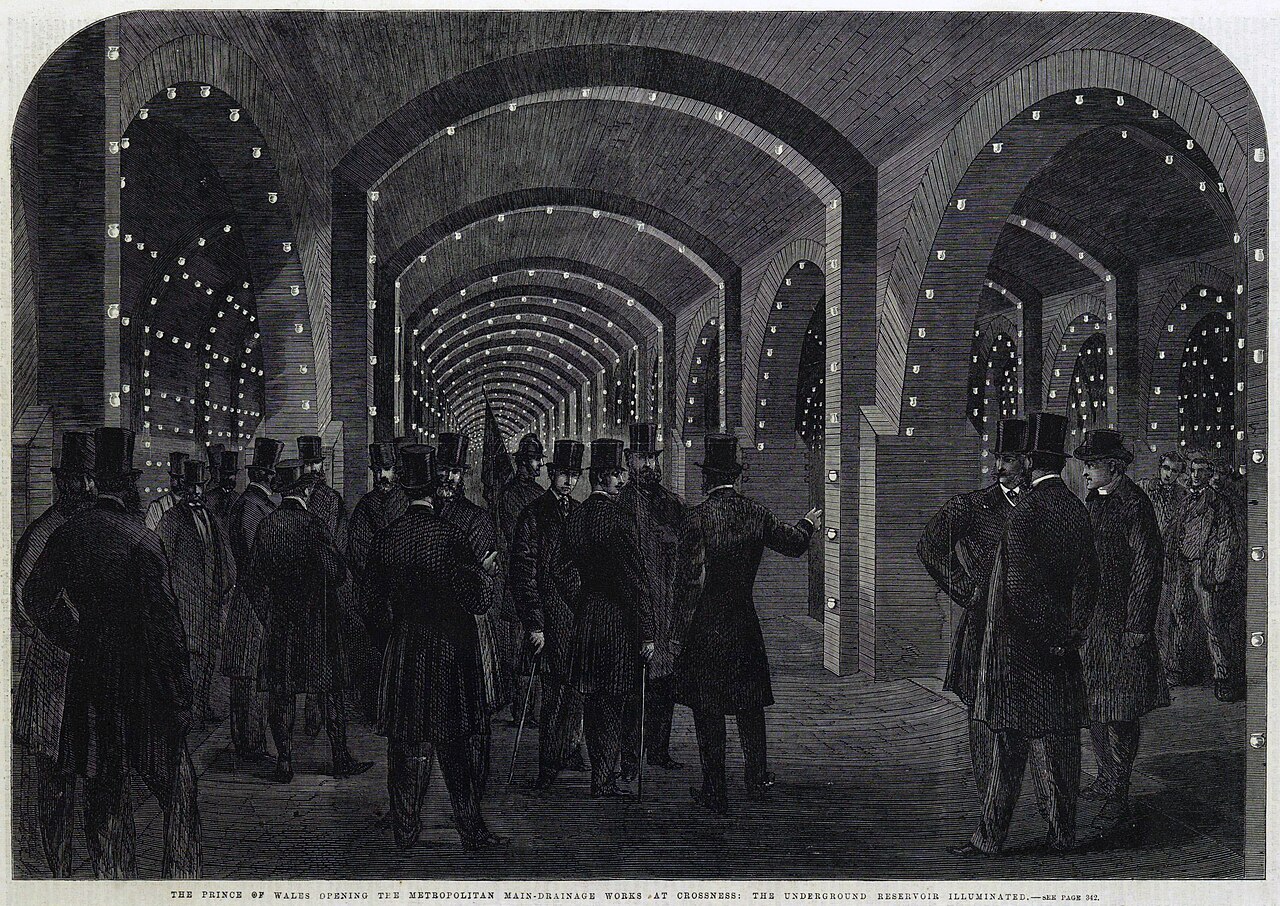
Crossness made the whole station visible as one machine: steam engines, pump rods and the civil structure were inseparable parts of the hydraulic duty.
Public domainWikimedia Commons
1.2.1The chain, in the order water meets it
The order is causal, not conventional. Screening comes before the pumps because the alternative is a ragged impeller. The wet well comes before the pumps because a pump that starts and stops with every toilet flush in the catchment burns out its motor. The check valve comes before the isolation valve because you have to be able to shut the main in and then open the pump up. Read the list as a sequence of answers to failures, and it stops being a parts list.
- Gravity sewer — brings the tributary flow to the station on the last of the available fall. It is the reason the station exists, and its invert elevation at the wall sets the highest water level the wet well may ever reach.
- Screening — a bar screen, basket or grinder that takes rags, wipes and debris out before they reach an impeller. Metcalf & Eddy, Wastewater Engineering, tabulates clear openings of 25–50 mm for manually cleaned bar racks. Skip it and you will be pulling a pump by hand.
- Wet well — the only storage in the station. It buys the volume between one pump start and the next, and its water surface is one of the two surfaces the static lift is measured between.
- Suction bell and suction pipe — delivers water to the impeller without drawing air with it. In a submersible station this collapses to a bellmouth on the pump itself; in a dry-pit station it is a real pipe through a wall, and §6.5 will ask whether the water arrives with enough pressure to avoid boiling.
- Pump — the only element in the chain that puts energy in. Everything else either holds water, guides it, or takes energy out of it.
- Check valve — stops the force main draining back down through an idle pump. Without one, two pumps on a common header simply recirculate through each other.
- Isolation valve — lets one pump be shut in and pulled while the station keeps running. It is downstream of the check valve so that the check valve itself can be serviced.
- Flow meter — records what the station actually delivered, which is how you learn about wear, infiltration and the difference between installed and real capacity.
- Discharge header — the manifold that joins both pumps onto one main. Unequal branches here are how a lead pump ends up refusing to share load with its partner.
- Force main — the pressurised pipe that carries the flow to the first place with fall again. Everything hard about a station is at one end of this pipe or the other.
- Discharge manhole — returns the flow to gravity and fixes the upper water surface. Without a defined receiving surface the static lift is not a number.
Two of those eleven are worth pausing on because their position is decided by maintenance rather than by hydraulics. In a steady-flow head calculation, two valves in series are interchangeable: their loss coefficients are simply added, and addition commutes. In a station they are not interchangeable at all. The isolation valve must be the last thing you can close between the pump and 900 m of full pipe, so it sits on the far side of the check valve. That distinction — a decision that the hydraulics cannot see but the operator lives with — is the subject of §1.2.3.
1.2.2Where the parcel actually spends its time
Take one station and follow one parcel. Two pumps, one duty and one standby, so the firm capacity is one pump at 30 L/s (476 US gpm, 0.68 MGD), and 30 L/s is also this station's stated design peak. Average dry-weather inflow 12 L/s (190 gpm) — so a peaking factor of exactly 2.5, which is a premise of the example and not something derived here. Where a peaking factor comes from, and why a catchment this small can be asked to carry 3.5 or more, is §1.4; leave the two numbers side by side without naming the factor between them and you have hidden the assumption that decides the pump. The 12 L/s arrives down a 250 mm sewer laid at 1.0% with Manning n = 0.013. A wet well 3.0 m × 3.0 m on plan with a 1.2 m band between pump stop and pump start. A 150 mm force main 900 m long, discharging into a manhole whose water surface sits at elevation 113.00 m against a wet well that works between 94.40 m and 95.60 m.
Upstream of the pump the water moves at the inflow, and it moves all the time. Downstream it moves at the pump flow, and only while the pump is running — which at this inflow is 600 s of every 1500 s cycle, or 40% of the day. Those are two different clocks, and the first mistake in a residence-time budget is to add them: 900 m of 150 mm main holds 15.9 m³, which is 8.8 min of pumping, but the parcel sitting in that main is not moving for the other 60% of the time. Nothing is wrong with the 8.8 min. It is simply not a residence time.
Put everything on one wall clock and the arithmetic is easier than it looks. Whatever enters the station leaves it, so averaged over a full cycle the throughput of every element is the inflow — the pump only decides whether the water goes in bursts — and the time a fixed volume holds a parcel is that volume over 12 L/s. On that clock total transit from the inlet to the outfall manhole is 40.8 min, of which the force main holds 22.1 min (54%) and the wet well's working volume 15.0 min (37%). The gravity sewer's last 120 m contribute 2.1 min. The six elements of station pipework between the wet well and the main — suction, pump, check valve, isolation valve, meter, header — hold the parcel for 28.1 s in total, which is 1.1% of its journey. Note which way that lands: it is the pipe, not the tank, that holds most of the journey, and on the running-time clock it looked like the other way round. This is not a bookkeeping nicety — dividing force main volume by average daily flow rather than by the pump rate is how sulfide generation is actually estimated, and §1.3 does exactly that.
Head and time are different books, and it is worth being explicit about that now, because the elements that dominate one do not dominate the other. The pump holds about 0.020 m³ of water, so a parcel is inside it for 0.7 s of pumping and 1.7 s of wall clock — and the pump is the only element that does any work. The wet well does no work at all and holds the parcel for a quarter of an hour. Residence time is nevertheless the quantity behind septicity: sewage held long enough without oxygen turns sulphate into hydrogen sulphide, which attacks concrete and kills people in confined spaces. So the wet well and the force main, the two elements that do the least, are the two that decide whether the contents arrive fresh.
And be careful what the wet well's 15.0 min is a measure of. It is the time to fill the working volume — the 10.8 m³ between pump stop and pump start — which is the right number for cycling and for the transit budget above. It is not the well's detention. Below the stop level sits another 0.8 m of water, 7.2 m³ that no cycle ever removes, so counting everything under the surface the well holds 18.0 m³ at the start level: 25.0 min at 12 L/s, and 17.5 min at mid-band. That gap matters in exactly one direction. Cycling cares only about the volume that moves; septicity cares about the water that sits, which is precisely the volume the cycling calculation throws away. §8.1 is where the benched floor that keeps that pocket small gets designed.
Interactive 3D instrument
One parcel, eleven elements — the chain in the order water meets it
A 3D instrument you drive yourself, one variable at a time. It needs JavaScript and WebGL, so it is not shown in this static copy of the page.
A compact station sketch can hide the lift, laydown and isolation space needed to remove a pump or valve. Hydraulic neatness is not operability if routine work requires dismantling the header.
Trace both the water path and the removal path. Show what must be isolated, lifted and kept in service during each credible intervention.
1.2.3Hydraulic, or operational
A hydraulic element exists for the water: it moves it, holds it, contains it, or conditions it before something downstream has to deal with it. An operational element exists for the people, so that they can isolate, measure, ventilate, power and survive the station. The test is who the element is for, not what sets its size — though the two usually agree, and where they agree it is worth saying how: the wet well's volume comes from a cycling calculation, the force main's diameter from a velocity window, the suction pipe's diameter from an approach velocity. Where they disagree is instructive rather than awkward. The bar screen is hydraulic — it is in the water's path and it exists to condition the water — but nothing about its size comes out of a head calculation: bar spacing is set by the solids you intend to catch. Hydraulics does not choose the operational elements either — the pipe they sit in does — but they still turn up on the bill.
| Element | Why it exists | Sized by | In the parcel's path? |
|---|---|---|---|
| Wet well | storage between starts; sets the suction water surface | hydraulics — cycling and detention | yes |
| Force main | carries flow to the next place with fall | hydraulics — velocity window | yes |
| Suction pipe and bell | feeds the impeller without air | hydraulics — approach velocity, submergence | yes |
| Check valve | stops reverse flow through an idle pump | hydraulics — closure behaviour, surge | yes |
| Bar screen | keeps rags off the impellers | solids, not head | yes |
| Isolation valve | lets one pump be pulled with the station running | the pipe it sits in | yes — operational |
| Flow meter | tells you what the station did | the pipe it sits in | yes — operational |
| Level sensors and floats | decide when the pump runs | the level band | no |
| Ventilation | keeps a confined space enterable | air changes, not water | no |
| Standby power | keeps the station a station during an outage | motor load | no |
| Telemetry and alarms | tells somebody before the overflow | nothing hydraulic | no |
| Access hatch and davit | gets the pump out | the pump's size and mass | no |
| Standby pump | firm capacity with the largest unit out of service | redundancy rule — see §1.4 | only when running |
The redundancy line in that table is a standard's requirement rather than physics: the Recommended Standards for Wastewater Facilities — the Ten State Standards — asks for at least two pumps and for the remaining units to handle the design peak with the largest unit out of service. §1.4 does that arithmetic. The point here is that the second pump is in the station for a reason no head calculation contains.
Operational does not mean free
The two operational elements in the parcel's path do cost head. Using the loss coefficients in src/core/hydraulics.js, an open plug valve is K = 1.0 and a magnetic flow meter is K = 0.2, so together they are 1.20 velocity heads. Both sit in the 150 mm main, where this station runs at 1.70 m/s and one velocity head is 0.147 m, so the two of them cost 0.176 m — about 1% of the 18 m lift, and roughly a sixth of the station's whole fitting budget of ΣK = 7.10. Small, and not zero.
That whole budget is 1.01 m, and getting there is not 7.10 × 0.147. A K is worth whatever the velocity in its own pipe makes it worth, and the three suction-side fittings — bellmouth, long-radius elbow, reducer, ΣK 0.50 — are in a 175 mm suction pipe running at 1.25 m/s, where a velocity head is only 0.079 m. So the budget is 0.50 × 0.079 in the suction plus 6.60 × 0.147 in the main. Charge all 7.10 at the main's velocity and you get 1.04 m: 3.3% high, and high in the direction that oversizes a pump. Lumping ΣK across diameters is the classic way to inflate a system curve, and §4.2 is a whole lesson on that species of bookkeeping error. What makes the valve and the meter operational is that hydraulics did not choose them; it only got the invoice. Module 4 prices every fitting in the budget properly.
1.2.4The two elements that decide the design
Of the eleven, two carry almost all of the design tension, and they are the two that hold the water. The wet well is squeezed from both ends. Make it small and the pump cycles hard: with the working volume V = plan area × band, one fixed-speed pump's cycle is t = V/(Qp − Qi) + V/Qi, which is shortest when the inflow is exactly half the pump rate and collapses there to 4V/Qp. Make it large and the contents sit long enough to go septic. The design lives between a motor's permitted starts per hour and a detention limit, which is why wet well volume is a range and never a single answer.
working volume      V  = 3.0 m x 3.0 m x 1.2 m      =  10.8 m3   (2 853 US gal)
fill at 12 L/s          10.8 / 0.012                  =   900 s  = 15.0 min
cycle at 12 L/s         10.8/(0.030-0.012) + 900       =  1500 s  = 25.0 min -> 2.4 starts/h
worst inflow            Qi = Qp/2 = 15 L/s
cycle there             4V/Qp = 4 x 10.8 / 0.030       =  1440 s  = 24.0 min -> 2.5 starts/h

the rule run backwards: what volume permits 6 starts/h at 30 L/s?
  V = Qp x (3600/6) / 4 = 0.030 x 600 / 4             =   4.5 m3  -> 0.50 m of band

so the 1.2 m band is generous on cycling: 2.5 starts/h worst case, against the
6-10 starts/h a motor this size is commonly permitted. Neither limit binds at
1.2 m. No detention ceiling has been stated in this lesson, and 25.0 min at
average flow (the full 18.0 m3, dead volume included) is inside the figures
usually quoted. What actually sets 1.2 m here is the sensor spacing and the
depth available; section 8.1 is where the cycling floor and the detention
ceiling are named and made to meet.
Cycling for this station, from pumpCycleTime and minWetWellVolume in src/core/hydraulics.js.
The force main is squeezed too, and from directions that do not meet in the middle. Flow is fixed by the pump, so diameter alone sets velocity — and a pipe is an area, so velocity goes as 1/D². At the fixed 30 L/s of this station, 150 mm gives 1.70 m/s, 200 mm gives 0.95 m/s, 250 mm gives 0.61 m/s and 300 mm gives 0.42 m/s. The Ten State Standards ask for a minimum of 2 ft/s in a force main, which is 0.6096 m/s exactly; common practice adds a scouring velocity of about 3.5 ft/s (1.0668 m/s) to be reached at least once a day, and self-cleansing in §1.3 and §8.2 goes into why. Note where that leaves the 250 mm option: it clears the 2 ft/s minimum by about 1.5 mm/s and never scours at all. At the other end, common practice holds a force main to somewhere around 2.5–3 m/s. That is not a threshold in any standard quoted here and not a law of physics; it is an acknowledgement that everything expensive about a station scales with the velocity you eventually have to destroy, which the next paragraph and §8.5 get to.
The upper end of that window is bounded too, and not by a rule of thumb. A sudden velocity change in a full pipe produces a pressure wave whose head rise is proportional to the velocity destroyed — Δh = a·ΔV/g, the Joukowsky result — so the 3.82 m/s that a 100 mm main would run at is buying a surge problem along with its scour, which is why Figure 1.2 puts a dashed ceiling under it rather than colouring it as a clean pass. §8.5 computes it. For now, notice the shape of the decision: the diameter that saves the most energy is the one most likely to silt, and the diameter that scours hardest is the one most likely to burst something. Neither end is a free choice, and the pump has not even been selected yet.
Check your understanding
Check your understanding
3 auto-graded questions with an explanation for every wrong answer. Requires JavaScript. (m1-l2-q1)
1.2.5What this lesson has deliberately not done
It has not computed a head. The 18 m quoted above is the static lift only — the gap between two water surfaces, 113.00 m at the outfall against a wet well working between 94.40 m and 95.60 m, so 17.4 m to 18.6 m depending on where the level sits, or 57.1 ft to 61.0 ft. That is already a range rather than a number, and it is not what the pump has to produce. Add the friction in 900 m of pipe and the 1.01 m of fittings counted above — which already contains the one full velocity head you throw away discharging into the manhole, the K = 1.0 exit on the end of the force main — and you have total dynamic head. Add that exit and a separate residual velocity head and you have charged the pump twice for the same water; the argument in totalDynamicHead that invites it is residualVelocityHeadM, and §4.3 is the lesson about not falling for it. Module 2 builds the accounting; Module 3 prices the friction.
It is worth seeing what the static part alone costs, because it is the floor under everything else. Raising one cubic metre of 15 °C water 18.0 m takes mgh = 999.13 × 9.80665 × 18.0 = 176.4 kJ, which is 0.0490 kWh/m³ and cannot be negotiated with. At a 75% pump and a 95% motor it becomes 0.0688 kWh/m³. Every metre of friction the design adds is paid on top of that, every day, for the life of the station.
- Total dynamic head, and why static lift is a range: §2.3 and §2.5.
- The friction in the 900 m, properly: §3.2.
- The 1.01 m of fittings, element by element and each at its own velocity: §4.1.
- Whether the pump can actually draw from the wet well without cavitating: §6.5.
- Why two pumps do not give twice the flow: §7.3.
- What the check valve does in the two seconds after the motor stops: §8.4.
One calculation from this lesson is worth having in your own hands, because it is the one you will do standing in front of a wet well with a tape measure. Implement it below.
Lab 1.2
Working volume, fill time, and the cycling check
Two functions, both of which you will use on real jobs. wetWellFill(planAreaM2, startLevelM, stopLevelM, qInLps) returns { volumeM3, fillMinutes } — the working volume between the pump start and pump stop levels, and the time to fill it at the given inflow. Note that the levels are elevations , so only their difference matters; a well whose band is 1.2 m has the same working volume whether it sits at 95 m or at 3 m above datum. startsPerHourWorst(volumeM3, qPumpLps) returns the worst-case starts per hour for a single fixed-speed pump. Cycling is fastest when the inflow is exactly half the pump rate, where the cycle collapses to 4 V / Q p , so this is the number you compare against the motor's permitted starts. Both flows arrive in litres per second ; everything else is metres, cubic metres and minutes. Graded in the browser against 6 assertions; the editor and harness require JavaScript.
Head, Loss and Lift · Module 1, Lesson 2