§ 5.4 Module 5 — The Hydraulic Profile
The Profile Along the Force Main
The grade line at a high point is the discharge water surface plus the friction still to be spent below it. Take the flow away and you take the friction away, and the line comes down onto the pipe.
By the end of this lesson
- Identify high points where air will collect and explain the loss they cause
- Check a profile for sub-atmospheric pressure and say what to do about it
- Explain why a rolling profile can be worse than a steady climb
5.4.1The clearance, and the line it is measured to
§5.3 delivered the water to the force main flange with a number on it. The remaining 1 200 m looks like bookkeeping — one diameter, one roughness, one length — and it is not, because out there the ground has an opinion. A force main follows the surface it is buried under, and every place that surface rises and falls again is a potential air-accumulation point. What decides whether that matters is where the grade line sits relative to the top of the pipe.
Draw the grade line from the wrong end and it is wrong everywhere. The only head on this main known without assuming anything is the receiving water surface: 27.30 m, at a submerged outlet, where the HGL just inside the pipe equals the water surface outside it. So march upstream — every station stands higher than the discharge by the friction still to be spent getting down to it. At 60 L/s (951 gpm) this main loses 6.50 m over its length, 0.542 m per 100 m at 1.222 m/s (4.01 ft/s), so the grade line is 33.80 m at the flange, 29.68 m at 0+760, 27.30 m where it started. Hazen-Williams at C = 140, the value tabulated for the new cement-lined ductile iron this main is built from, gives 6.34 m: 2.6% apart, so the gradient is not the uncertain part of this drawing.
What the grade line has to clear is the crown, not the centreline: air collects at the top of the bore, so the top of the bore is where the pressure is checked. On a 250 mm main the crown stands 125 mm above the centreline, and at a marginal high point 125 mm is the answer — check to the centreline and this alignment reports 0.225 m of clearance at 1+050 where the honest figure is 0.100 m.
A high point is a local maximum of the crown, and nothing else is. Between two survey shots the crown is straight, so a maximum can only sit at a shot — the survey interval, not the calculation, sets how much of the profile you can see. This alignment has two: 0+760, crown 28.80 m, and 1+050, crown 27.20 m.
| Flow | HGL at 0+760 | Clearance | HGL at 1+050 | Clearance | Governs |
|---|---|---|---|---|---|
| 0 (pumps off) | 27.30 m | −1.50 m | 27.30 m | +0.10 m | 0+760 |
| 20 L/s | 27.60 m | −1.20 m | 27.40 m | +0.20 m | 0+760 |
| 47.05 L/s | 28.80 m | 0.00 m | 27.81 m | +0.61 m | 0+760 |
| 60 L/s (design) | 29.68 m | +0.88 m | 28.11 m | +0.91 m | 0+760 |
| 80 L/s | 31.44 m | +2.64 m | 28.71 m | +1.51 m | 1+050 |
Read the last column first. Which high point governs changes hands at 60.56 L/s, for a reason that is geometry rather than hydraulics: 0+760 has 440 m of main below it to lift its grade line and 1+050 has only 150 m. Set the clearances equal and the 27.30 m cancels, leaving the friction over 440 m less that over 150 m equal to the 1.60 m the crowns differ by — so, friction being linear in length, the crossover is the flow at which 290 m of this main loses 1.60 m. Hence the rule: check every local maximum. Checking only the tallest misses the station that governs at 80 L/s.
5.4.2The worst case has no flow in it
Stop the pumps. Every loss term carries Q, so at zero flow there is no friction to spend and the grade line is flat at 27.30 m from flange to discharge. Nothing has failed: the check valve has shut and the main stands still, full, held up at its far end by the receiving water. Now put the crown beside it. At 0+760 the crown is 28.80 m — 1.50 m above the grade line, −14.7 kPa (−2.13 psi) at the top of the pipe. From 0+726.7 to 0+840.8, a reach of 114.10 m (374 ft), this main stands above its own grade line and so below atmospheric — every idle hour, which on a small station is most of the day.
That is the inversion to carry out of this lesson. Clearance at a high point is worst at the lowest flow and worst of all at none, because the grade line there is the discharge water surface plus the friction still to be spent downstream. "Check it at peak flow" sounds like conservatism and selects the one condition in which the summit is comfortable: at 60 L/s it has 0.88 m over the crown. It has never been fine at 3 a.m.
How far a vacuum can pull water, and who found out
The number bounding this discussion was measured before anyone designed a pump station. In Rome, about 1641, Gasparo Berti stood a long lead tube against the wall of his house, filled it with water and sealed the top. The water fell back a little and stopped, leaving a space above it that nothing could get into; Raffaello Magiotti, Athanasius Kircher and Niccolò Zucchi are among the witnesses named in the surviving accounts. The height at which that column settled is the quantity this lesson computes as 10.17 m of water.
Evangelista Torricelli, in Florence in 1644, repeated the idea with mercury — fourteen times denser, so a tube under a metre would do — and gave the interpretation in letters to Michelangelo Ricci of 11 and 28 June 1644: the column is held up by the weight of the air outside. On 19 September 1648 Florin Périer carried a barometer up the Puy de Dôme for his brother-in-law Blaise Pascal and found the column shorter at the summit than at the foot — which is why a station at 1 200 m of elevation pumping 25 °C wastewater has 8.65 m of margin where a sea-level station at 15 °C has 10.17 m.
So a crown below its grade line has three states, not two. Down to about 10.17 m of vacuum here — (patm − pvapour)/ρg at 15 °C and sea level, the value §2.2 derives independently — the water stays liquid and the pipe stays full: sub-atmospheric. Below it the water boils at ambient temperature and the column parts: column separation, which fills the crown with vapour and slams when it collapses. At 1.50 m under, this summit is nowhere near separating — and sub-atmospheric is a design finding anyway: dissolved or entrained gas may accumulate, joints can leak inwards, and the pipe cannot vent itself.
For potable water that same 1.50 m ends the conversation. Sub-atmospheric pipe is a contamination pathway rather than an inefficiency, so distribution practice requires positive pressure at all points at all times: the Ten State Standards call for a minimum of about 138 kPa (20 psi), which is 14.06 m of water, and about 241 kPa (35 psi) normally. The physics is identical to the sewage case; the acceptance criterion is not, and it belongs on the drawing.
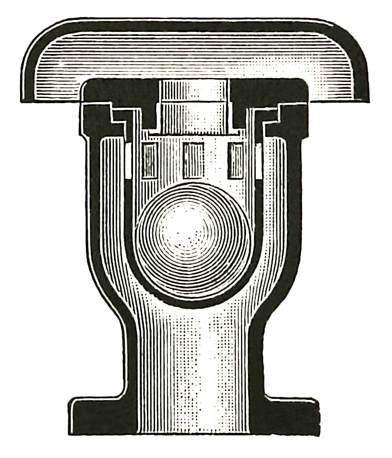
This 1905 cutaway already shows the central idea: air collects at a high point, the float falls, and an opening is exposed. Modern combination valves refine the duties, not the reason for the device.
Dr. Mirko JungePublic domainWikimedia Commons
Interactive 3D instrument
The grade line, the crown, and the air between them
A 3D instrument you drive yourself, one variable at a time. It needs JavaScript and WebGL, so it is not shown in this static copy of the page.
A positive steady pressure can disappear during trip, restart or check-valve closure. Conversely, an air valve can change the transient that justified its location.
Use the steady profile to identify vulnerable points, then carry those points into the transient and air-management review.
5.4.3What the air costs once it is there
Air arrives three ways, none unusual. It is left behind after filling or maintenance, because a main fills along its bottom and traps air at every summit. It is dragged in at the pump, since a wet well drawn into a vortex entrains it — one reason §8.3 cares about submergence. And dissolved gas can separate as pressure falls below its local saturation condition; here the 114 m reach below atmospheric every idle hour is the vulnerable reach. Wastewater often carries dissolved and entrained gas, so that reach needs an explicit air-management check.
A pocket at a high point makes the water squeeze underneath and then re-expand. The contraction is nearly free, as a guided acceleration usually is; the re-expansion is not. Borda-Carnot puts that loss at (v₁ − v₂)²/2g, so with the pocket taking a fraction β of the bore the coefficient on the full-bore velocity head is (β/(1 − β))² — indifferent to small pockets, then running away. Read the figures as a floor on the penalty: a real pocket stretches down the descending leg, so the water accelerates under it over a distance rather than at a station.
- β = 0.1: 0.001 m at 60 L/s — below measurement.
- β = 0.3: 0.014 m, 0.2% of the main's 6.50 m of friction.
- β = 0.5: K = 1 exactly, so the loss is exactly one velocity head, 0.076 m.
- β = 0.8: K = 16, 1.22 m — 19% of the whole main's friction, from one pocket.
- β = 0.9: K = 81, 6.17 m, nearly doubling the head the pump must make.
5.4.4Where the valves go, and what they have to pass
An air valve is not one device with one duty; there are three, and confusing them is how a schedule fills with the wrong hardware. Air release is a small orifice letting accumulated air out while the main runs; it works by internal pressure, so it does nothing at a crown already below atmospheric. Air and vacuum is a large orifice passing bulk air both ways — out as the main fills, in as it drains — closing when water reaches it. A combination valve carries both, which is what a high point usually needs. AWWA Manual M51 and the valve standard AWWA C512 set out this vocabulary.
- At every local maximum of the crown — that is where air goes, and nowhere else.
- At the top of a long ascending run, and along long level runs where the pipe is nearly parallel to its own grade line and a pocket has no reason to move.
- Wherever the profile puts the crown above the grade line in any credible condition, since that reach cannot vent itself.
- And for the vacuum duty, wherever a drain-down or a downstream break would leave a reach unable to admit air as fast as water leaves.
The last of those sizes the orifice, and the number is larger than people expect. The leg from 0+760 down to 0+900 falls 2.60 m in 140 m, a slope of 1.86%. Flowing full under its own slope — friction over the leg equal to the fall — it passes 113.6 L/s (1 801 gpm) at 2.31 m/s, nearly twice the design flow, so the vacuum orifice must admit about 6.8 m³ of air a minute (241 cfm) while the main empties. On ductile iron a vacuum is a nuisance; on thin-wall PVC, HDPE or steel it is a buckling check. The outward duty is the reverse: this main holds 58.90 m³ (2 080 ft³) of air when empty, and filling at the 0.3 m/s (1 ft/s) rate commonly specified takes 14.7 L/s for a little over an hour.
Why the best air valve is often no air valve
On a sanitary force main an air valve is a maintenance liability: grease and rag foul the seat, and a valve that fails shut is invisible while one that fails open discharges sewage into a chamber at grade. It needs an isolation valve under it, a flushing connection, and an inspection visit that will actually happen. Which is why the first answer to a high point is usually to delete it: here 1.50 m of extra cover through 0+760, tapered out over 240 m either side, puts the crown exactly on the static grade line, and 2.00 m puts it 0.50 m above. One deeper trench against a valve, a chamber and a thirty-year obligation — and the profile is the only thing that tells you the trade exists.5.4.5The shutdown sheet, and what is not on it yet
A complete force main profile is therefore two drawings of one pipe. The running sheet, at a stated flow, grade line tilted, every high point annotated with its clearance. And the shutdown sheet: same ground, same crown, one flat line at the receiving water surface, the reach above it dimensioned. Both state their vertical exaggeration — at 10:1 a 1.86% slope looks like a hillside. The shutdown sheet is the one that gets left off, and the one that decides the valve schedule.
One consequence worth having in advance, because it looks like an error: aging improves high-point clearance. Hold the flow at 50 L/s and roughen this wall from ε = 0.10 mm to ε = 1.60 mm — §3.5's upper-bound thirty-year allowance — and friction over the main goes from 4.59 m to 8.41 m, taking the clearance at 0+760 from +0.18 m to +1.59 m. The pipe is failing at its job and passing this check more comfortably every year. The corollary bites: commissioning day is the worst running case for a high point, and nobody draws it.
What this profile does not contain yet is anything that moves. The static line is where the main settles after the pumps stop, not what happens while it is stopping: the downsurge travelling up the main on a pump trip can pull a high point far below its static value, and column separation is a transient before it is a steady state. That is §8.5, which takes the shutdown profile drawn here as its starting condition. The pump remains a boundary condition supplying whatever head is demanded, and §5.5 asks what a reviewer needs written on both sheets to believe a word of it.
Lab 5.4
The high-point check, as four functions you can keep
This is the arithmetic of a force main profile, and it is small enough to carry with you. Everything is SI: stations and elevations in metres, flow in m³/s, head in metres of water. The station is §1.5's — 1 200 m of 250 mm main, 1.40 m of cover, discharging submerged at 27.30 m — and setup hands you groundAt(sM) , crownAt(sM) , frictionOver(qM3s, lengthM) , SURVEY , HIGH_POINTS , DISCHARGE_WATER_M , MAIN_LENGTH_M , D_M , pipeArea and velocityHead . hglAt(stationM, qM3s) — the hydraulic grade line elevation, m. March from the discharge, not from the pump: the grade line at a station is the receiving water surface plus the friction still to be spent between that station and the discharge. At the discharge itself it must return exactly 27.30 m at every flow, and that is graded. governingHighPointStation(qM3s) — of the stations in HIGH_POINTS , return the one with the least clearance above the crown at this flow. Not the highest crown; the least clearance. Which one that is changes with flow. subAtmosphericLengthM(qM3s) — the total length of main, m, whose crown stands above the grade line. Sample it or solve it exactly; either passes. Zero is a legitimate answer. pocketLossM(qM3s, dM, airFraction) — the Borda-Carnot loss across a trapped pocket occupying airFraction of the bore: the water passes through the remaining area and re-expands, and the loss is (v₁ − v₂)²/2g with v₁ the velocity in the reduced area. Derive the coefficient rather than looking it up; there is no fitted constant in it. Graded in the browser against 7 assertions; the editor and harness require JavaScript.
Check your understanding
Check your understanding
3 auto-graded questions with an explanation for every wrong answer. Requires JavaScript. (m5-l4-q1)
Numbers from src/scenes/m5/profile-force-main.js, on §1.5's surveyed alignment. The pump is still a boundary condition; the transient is still Module 8.