§ 6.1 Module 6 — Pumps
How a Centrifugal Pump Makes Head
The impeller adds velocity; the casing decides how much of it leaves as pressure.
By the end of this lesson
- Describe the energy conversion from impeller to discharge flange
- Explain why a pump has a curve rather than a rating
- Predict qualitatively how head varies with flow and why
6.1.1Follow one parcel through the machine
Water enters near the eye of a rotating impeller, turns with the vanes, and leaves near the rim with more angular momentum than it had at entry. The shaft has done work on the water. Expressed per unit weight, that work is head: the elevation through which the same energy could lift the water. Head is therefore a property of the energy transfer, not a synonym for discharge pressure.
The passages widen from eye to rim and the casing collects the high-speed streams. A volute grows in area around the circumference; a diffuser uses stationary vanes. Both slow the mean flow and recover part of its velocity head as static pressure. Recovery is never complete: incidence, separation, disk friction, leakage through wear-ring clearances, and mixing turn shaft work into heat and disorder.
- Eye: low absolute pressure admits the suction flow; poor approach flow first shows up here as cavitation or unequal vane loading.
- Vanes: torque changes the water’s angular momentum; diameter and tip speed set the available energy scale.
- Volute or diffuser: converts velocity into pressure while collecting flow; it does not create the energy.
- Discharge flange: the useful result is total head between suction and discharge reference sections, not one pressure gauge alone.
From wheels to an equation
Leonhard Euler’s eighteenth-century turbomachinery relation connected impeller torque to the change in angular momentum of the fluid. Modern computational models add detail, but pump selection still rests on that accounting: shaft work in, hydraulic energy out, losses between.
The preserved Prince Consort engine separates the energy source, reciprocating mechanism and pump below — a physical reminder that a pump adds head through a machine, not at a mathematical point.
Nathusius2CC BY-SA 4.0Wikimedia Commons
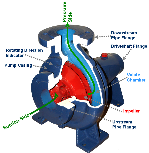
A cutaway model makes the energy path tangible: liquid enters at the impeller eye, gains angular momentum in the rotating passages, then trades velocity for pressure in the volute.
FantaguPublic domainWikimedia Commons
6.1.2Why the result is a curve
At zero delivery a closed discharge can support the pump’s shutoff head, but flow inside the casing still recirculates and heats the liquid. As the valve opens, more water crosses the impeller each second. Incidence and hydraulic losses change with that flow, so the head the same machine develops changes too. The useful object is a pump curve, Hp(Q), not a single flow/head rating.
For an ordinary radial-flow centrifugal pump at fixed speed and diameter, head generally falls as flow rises. That is a measured relationship, not permission to extend a convenient parabola forever. The manufacturer’s tested range ends before unstable low-flow operation on the left and mechanical or power limits at runout on the right.
Interactive 3D instrument
Inside the casing — then outside it
A 3D instrument you drive yourself, one variable at a time. It needs JavaScript and WebGL, so it is not shown in this static copy of the page.
Pump head is the change in total head between suction and discharge reference sections. One gauge omits suction pressure, elevation difference and velocity-head change.
Define both measurement sections and convert their pressure, elevation and velocity terms to a common head basis.
6.1.3The system chooses the delivery
The pipe system owns a second relationship. Its head demand equals static lift plus losses that grow roughly with flow squared in turbulent service. The actual operating point is where demanded head equals supplied head. Put the same pump on a shorter, larger main and the intersection moves right; raise the receiving reservoir and it moves left. Nothing inside the pump “sets” either flow.
Q = 0.080 m³/s    H = 30.0 m
P_water = ρgQH
        = (999 kg/m³)(9.80665 m/s²)(0.080 m³/s)(30.0 m)
        = 23.512 kW
At η_pump = 0.78, P_shaft = 23.512/0.78 = 30.144 kW.
Water power at one operating point
This calculation prices an operating point after the intersection is known. It does not predict that the pump will deliver 80 L/s. Module 7 will earn the intersection; this lesson keeps the station, valves, wet well, and controls outside the machine boundary.
6.1.4Failure at either end of the curve
Near shutoff, internal recirculation, radial load, temperature rise, and vibration can dominate. Near runout, power, NPSH required, velocity, and motor load can exceed the selected limits. “The pump can reach that point on paper” is not the same as “the pump may operate there continuously.” Use the manufacturer’s allowable operating region and minimum continuous stable flow.
Check your understanding
Check the boundary
1 auto-graded question with an explanation for every wrong answer. Requires JavaScript. (m6-l1-q1)
Lab 6.1
Implement hydraulic and shaft power
Write pumpPower(qM3s, headM, efficiency) returning shaft power in kW. Use ρ = 999 kg/m³ and g = 9.80665 m/s². Graded in the browser against 2 assertions; the editor and harness require JavaScript.
Examination score
The scorecard totals this page’s graded work as you go. It requires JavaScript.
The curve belongs to the pump. The point on it belongs to the system.